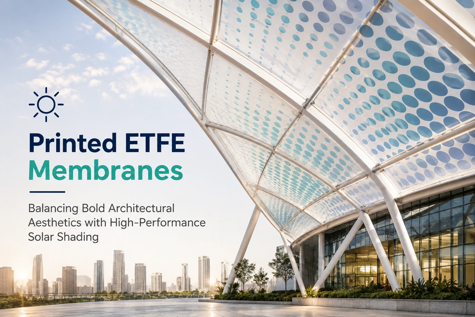
ETFE is a lightweight fluoropolymer used in roofs, façades, skylights, and large-span building envelopes. Its high transparency can bring plenty of natural light into a building, with transparent ETFE transmitting around 95% of visible light. However, the same transparency can also allow significant solar energy to enter, which may increase cooling needs and cause glare or thermal discomfort. Printing a controlled pattern onto the foil can help manage this solar exposure while keeping the membrane visually open. The global ETFE market is projected to reach USD 0.58 billion in 2026, up from USD 0.54 billion in 2025, according to Fortune Business Insights.
In this article, we will discuss how printed ETFE controls sunlight, how fritting patterns affect daylight and glare, and how architects can balance aesthetics with solar and thermal performance.
How Does ETFE Printing Control Sunlight?
A clear ETFE foil lets most incoming solar radiation pass through. That is useful for daylight, but it can also cause unwanted heat gain.
Printing adds an opaque or semi-opaque pattern to selected areas of the foil. The printed area blocks or reflects part of the incoming radiation. The open areas continue to transmit daylight.
This creates a simple design principle:
- More printed coverage means less solar transmission.
- Less printed coverage means more daylight.
- Pattern density can be adjusted to meet project requirements.
- Different patterns can change how light is distributed indoors.
- Printing can also be used for architectural graphics.
The result depends on the foil thickness, number of layers, ink or coating, pattern, coverage ratio, orientation, and complete cushion design. A single foil should therefore not be assessed in isolation.
Research has shown that different printed ETFE surfaces can produce different light-scattering profiles. This matters because two patterns with similar coverage can still create different indoor lighting conditions.
What Are ETFE Fritting Patterns?
Fritting is the process of applying a printed pattern to the ETFE surface to control light transmission. Patterns can range from small dots to lines, grids, gradients, graphics, and larger geometric forms.
The pattern is not simply a visual choice. Its coverage and density affect how much light and solar energy can pass through the membrane.
Common design options include:
| Pattern approach | Main effect | Suitable design goal |
|---|---|---|
| Small dots | Moderates daylight across the surface | Balanced daylight |
| Large dots | Creates stronger areas of shade | Higher solar control |
| Dense printing | Reduces transmission | Stronger heat control |
| Gradient pattern | Changes shading across the surface | Location-specific control |
| Graphic printing | Adds visual identity | Architectural expression |
| Layered printing | Provides additional control | Complex roof or façade systems |
Research into different dot patterns has also found differences in indoor daylight levels. One 2024 study compared several ETFE dot patterns and found that a 16 mm dot pattern produced favorable daylighting results compared with smaller dots and clear foil.
This shows why pattern selection should be tested rather than based only on appearance.
How Does ETFE Printing Affect Daylight and Glare?
Daylight is one of the main reasons architects specify ETFE. The material can provide high levels of natural light while keeping the envelope lightweight. The challenge is controlling excessive brightness.
A large transparent roof can create bright patches on floors, furniture, and work surfaces. Direct sunlight can also produce uncomfortable reflections and high contrast. Printed areas can reduce the amount of direct solar radiation entering the space and help distribute daylight more evenly.
This can support better visual comfort when the pattern, orientation, and coverage are selected correctly.
Studies of ETFE façade systems have shown that changes in the foil's optical properties can affect daylight distribution and glare. In one simulation study, switchable ETFE façades improved useful daylight levels and reduced calculated glare under certain climate and façade conditions.
The key point is simple: more shading is not automatically better. Too much printing can reduce useful daylight and increase the need for artificial lighting.
How Is the G-Value of ETFE Controlled?
The G-value describes the fraction of solar energy that enters a building through a transparent or translucent envelope. A lower value generally means less solar heat enters the space.
Clear ETFE can have a high solar transmission. One technical data source lists a G-value of about 0.95 for a 100-micron transparent ETFE foil. Actual values for a complete system can be lower when printing, multiple layers, or other treatments are used.
This makes G-value optimization a design task rather than a fixed material property.
You need to consider:
- Foil thickness.
- Printed coverage.
- Number of ETFE layers.
- Cushion geometry.
- Building orientation.
- Local solar conditions.
- Window or roof area.
- Internal heat gains.
- Daylight requirements.
Some ETFE design references report that two-layer systems with printed top surfaces can achieve G-values around 0.48, while three-layer systems may reach lower values. These figures are project-dependent and should not be treated as universal performance values.
How Can Printed ETFE Support Façade Design?
The main benefit of printed foil is that solar control need not look like a separate technical layer. The printed pattern can become part of the architectural composition. Dots can create rhythm. Lines can follow structural geometry. Gradients can respond to different sun exposures. Large graphics can create a strong visual feature.
This gives architects more control over facade design without relying entirely on conventional external blinds or fixed shading devices.
The approach is also useful for large roofs and skylights where conventional shading systems may add weight, structure, moving parts, or maintenance requirements. However, the pattern still needs to meet measurable performance targets. A visually attractive design that allows excessive solar heat can create problems for the building later.
What Should You Check Before Choosing a Printed ETFE Pattern?
The best pattern starts with building performance, not artwork. Before selecting a final print, review:
1. Solar exposure
Study the building orientation and local sun path. South-, east-, and west-facing surfaces can have different solar conditions depending on the location.
2. Daylight targets
Check how much natural light the space needs. A heavily printed membrane may reduce daylight too much.
3. Thermal performance
Model solar heat gain and cooling loads. Do not assume that a darker or denser print will automatically produce the best result.
4. Indoor glare
Review direct sun, reflections, contrast, and occupant sight lines. This is especially important for offices, schools, transport buildings, and spaces with screens.
5. Pattern scale
A pattern that looks clear from close range may appear almost uniform from inside the building. The viewing distance should be considered during design.
6. Cushion configuration
For multi-layer ETFE systems, the position of the printed layer can affect the overall optical and thermal result.
7. Maintenance and durability
ETFE has strong chemical and weather resistance, but printed surfaces still need to be assessed for their behavior under UV exposure, movement, cleaning, and long-term use.
Can Custom ETFE Printing Be Used for Large Architectural Projects?
Yes. ETFE printing can be incorporated into custom architectural membranes, allowing designers to specify patterns based on performance or appearance.
The printing does not have to cover the entire surface at the same density. A project can use different coverage levels in different areas.
For example, a roof could use denser printing over areas exposed to strong sun and lighter printing where daylight is needed. This approach can help avoid treating the whole roof as if it has identical solar conditions.
CForce lists ETFE cushion structures and customized printing among its architectural membrane work. Its project information also describes a multilayer ETFE cushion canopy on Shura Island, featuring colored ETFE with customized printing.
How Should Architects Design Printed ETFE for Better Performance?
A practical workflow can keep the process simple.
Step 1: Define the Building Requirements
Start with the room use, orientation, daylight targets, thermal loads, and occupant needs. Offices, stadiums, retail spaces, airports, and public areas may require different solutions.
Step 2: Test the Base ETFE System
Model the clear foil and the proposed number of layers first. This gives you a baseline for light and solar transmission.
Step 3: Compare Print Options
Test several coverage ratios and pattern types. Compare daylight, solar heat gain, and glare rather than judging the pattern from a visual sample alone.
Step 4: Adjust the Pattern
Use different densities where solar exposure changes. A uniform print may not be the most efficient choice for a large building.
Step 5: Review the Full System
Check the final cushion or façade assembly. Optical performance depends on the complete system, not only the foil.
Step 6: Validate the Final Design
Use simulation, technical data, and project-specific calculations before fabrication. This helps reduce the risk of choosing a pattern that looks good but performs poorly.
CForce Group's published ETFE information describes single-layer and multi-layer systems, including the use of printed foil and dynamic shading approaches in multi-layer cushions.
Why Does Printed ETFE Matter for Future Building Design?
ETFE gives architects a lightweight way to create large transparent or translucent building surfaces. Printing adds another layer of control.
The strongest applications treat the membrane as part of the building's environmental design. The pattern can respond to sun exposure, daylight needs, indoor comfort, and architectural intent simultaneously.
The material should still be specified carefully. ETFE does not automatically solve overheating, glare, or energy use. Its results depend on the complete envelope and the local climate.
For architects and façade teams, the useful approach is to treat the print as a performance parameter as well as a visual element.
Conclusion
Printed ETFE membranes can give buildings a distinctive appearance while providing a practical way to control sunlight. The key is to connect the pattern to measurable targets for daylight, solar heat gain, and occupant comfort.
Good design does not start with the most complex graphic. It starts with the building's orientation, climate, use, and performance needs. CForce is one example of a contractor working with ETFE cushion structures and customized printed systems in architectural projects.
For designers considering this material, the best results come from testing the complete membrane system before fabrication. CForce published project information shows how customized ETFE printing can be incorporated into large architectural structures.
Frequently Asked Questions
1. Is ETFE suitable for solar control?
Yes. Clear ETFE allows high light and solar transmission, but printing, multiple layers, and other treatments can reduce solar transmission. The final performance depends on the complete system and project conditions.
2. Does printing ETFE reduce natural daylight?
It can. The effect depends on the printed area, pattern density, foil properties, and number of layers. A carefully selected pattern can reduce excessive sunlight while retaining useful daylight.
3. Can ETFE patterns be customized?
Yes. ETFE can use standard or project-specific printed patterns. Designs can range from dot patterns and gradients to larger graphic elements.
4. Is ETFE better than glass for every building?
No. ETFE and glass have different strengths. ETFE is lightweight and highly transmissive, while glass offers different thermal, acoustic, structural, and visual properties. The right choice depends on the building, climate, span, performance targets, and budget.
